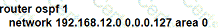
Refer to the exhibit.
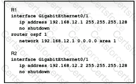
A network engineer started to configure two directly-connected routers as shown. Which command sequence must the engineer configure on R2 so that the two routers become OSPF neighbors?
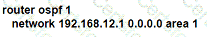
A)
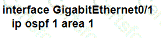
B)
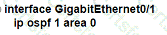
C)
D)
What is the function of a server?
Refer to the exhibit.
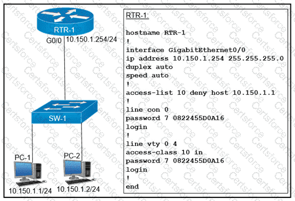
An access list is created to deny Telnet access from host PC-1 to RTR-1 and allow access from all other hosts A Telnet attempt from PC-2 gives this message: " % Connection refused by remote host " Without allowing Telnet access from PC-1, which action must be taken to permit the traffic?
Why is TCP desired over UDP for application that require extensive error checking, such as HTTPS?
How does CAPWAP communicate between an access point in local mode and a WLC?
Which access point mode relies on a centralized controller for management, roaming, and SSID configuration?
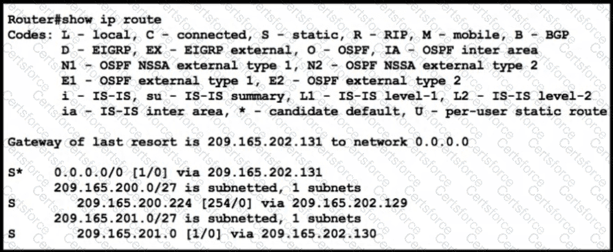
Refer to the exhibit.
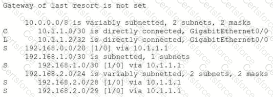
An engineer is checking the routing table in the main router to identify the path to a server on the network. Which route does the router use to reach the server at 192.168.2.2?
How are VLAN hopping attacks mitigated?
What prevents a workstation from receiving a DHCP address?
What does physical access control regulate?
Which HTTP status code is returned after a successful REST API request?
What is a difference between RADIUS and TACACS+?
Why was the RFC 1918 address space defined?
Refer to the exhibit.
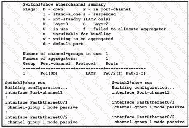
Which change to the configuration on Switch?
allows the two switches to establish an EtherChannel?
What is the path for traffic sent from one user workstation to another workstation on a separate switch In a three-tier architecture model?
Refer to the exhibit.
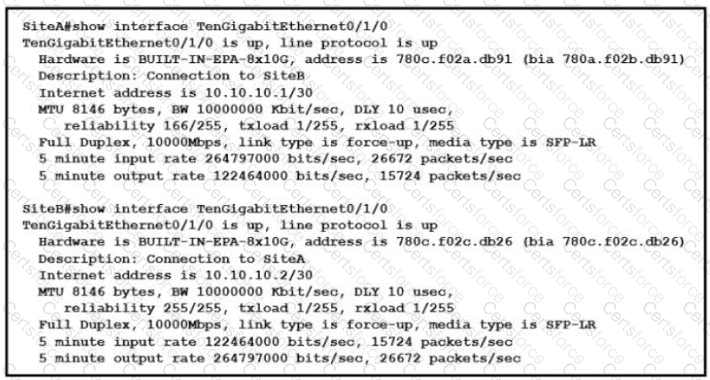
Shortly after SiteA was connected to SiteB over a new single-mode fiber path users at SiteA report intermittent connectivity issues with applications hosted at SiteB What is the cause of the intermittent connectivity issue?
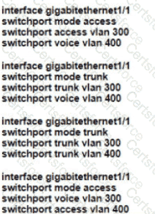
Refer to the exhibit.
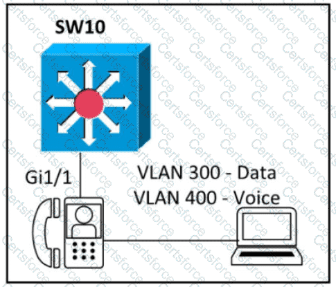
An engineer must configure GigabitEthernet1/1 to accommodate voice and data traffic Which configuration accomplishes this task?
What are two characteristics of a public cloud implementation? (Choose two.)
Refer to the exhibit.
Which command configures a floating static route to provide a backup to the primary link?
An office has 8 floors with approximately 30-40 users per floor What command must be configured on the router Switched Virtual Interface to use address space efficiently?