To answer this correctly, it is vital to distinguish between VSF (Virtual Switching Framework) and VSX (Virtual Switching Extension).
VSF (Virtual Switching Framework) Logic: The CX 6200 and 6300 series use VSF to form a " stack. " In a VSF stack, multiple physical switches operate as a single logical device with a single control plane and a single configuration file.
LAG Configuration in VSF: Because a VSF stack is a single logical entity, creating a Link Aggregation Group (LAG) that spans multiple members is handled exactly like a standard LAG on a single switch. You simply create the interface lag X and then assign physical ports from different members (e.g., member 1 and member 2) to that same LAG ID.
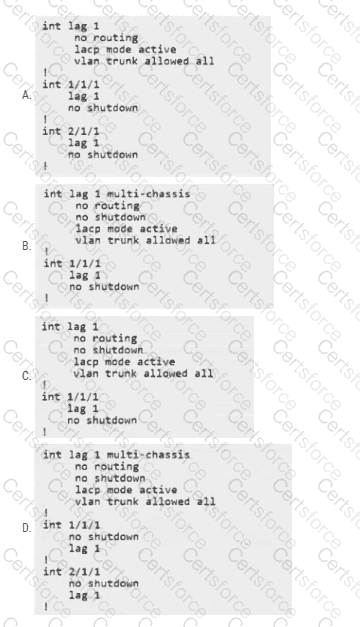
The " multi-chassis " Keyword: The keyword multi-chassis (seen in Options B and D) is specific to VSX, which is used on high-end switches like the CX 6400 and 8000 series. VSX involves two separate control planes that synchronize information. In VSX, you must use the multi-chassis command to let the switches know the LAG is split across two different chassis. In VSF, this keyword is not used and would result in a syntax error on a 6200 switch.
Analyzing the Options:
Option A (Correct): It uses standard interface lag 1 syntax. It assigns port 1/1/1 (from member 1) and port 2/1/1 (from member 2) to the same LAG. This perfectly fulfills the requirement for redundant ports from both switches in a VSF stack.
Option B: Incorrect because it uses the multi-chassis keyword (VSX only).
Option C: Incorrect because it only configures a port from one switch (1/1/1), failing the requirement for redundancy across both switches.
Option D: Incorrect because it uses the multi-chassis keyword (VSX only).
Key Takeaway for the ACP-S Exam: * VSF (6200/6300) = Standard LAG configuration across members.
VSX (6400/8000) = Requires multi-chassis keyword under the LAG interface.


Submit